Robot navigation using camera systems
Camera systems are designed for accurate navigation in production where positioning without feedback is no longer sufficient.
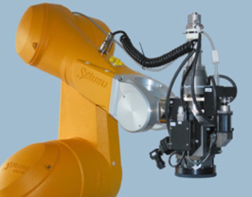
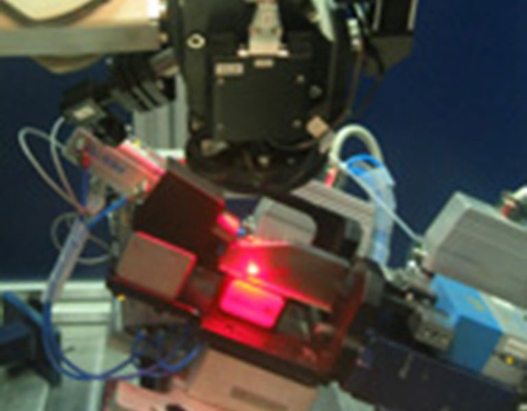
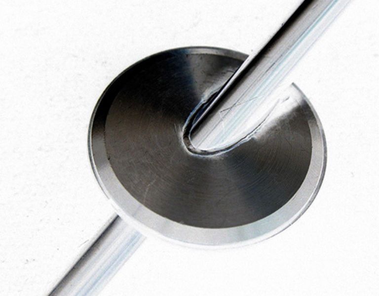
An example of use is 3D robot navigation during laser welding, where high precision welding is required. To accomplish this task, an integrated camera system based on the laser triangulation method was inserted into the Trumpf welding head. To achieve the required accuracy of 0.02mm, a unique 3D calibration was developed. The implemented solution ensures that the weld is made at the desired location and has the prescribed quality and strength.
The routine coordinate measurement and correction sequence typically takes less than 1s. The scanned data is archived for the possibility of further statistical processing with the option of sending the resulting values to the superior system.
Other examples of camera systems include: accurate product manipulation, quality control (dimensions and shapes) performed by a robot, relocation of generally placed products, robotic scanning of larger product areas, etc.
| Parameter | Value | Unit |
|---|---|---|
| The smallest size of the monitored area | 8×8 | mm |
| The biggest size of the monitored area | 200×200 | mm |
| Camera resolution | 1600×1200 | px |
| Measuremet accuracy | from ± 0,01 | mm |
| Scanning velocity | < 1 | s |
| Ambient temperature | 5 – 35 | °C |
| Voltage | 24 | V |
| Communication interface | Ethernet | – |
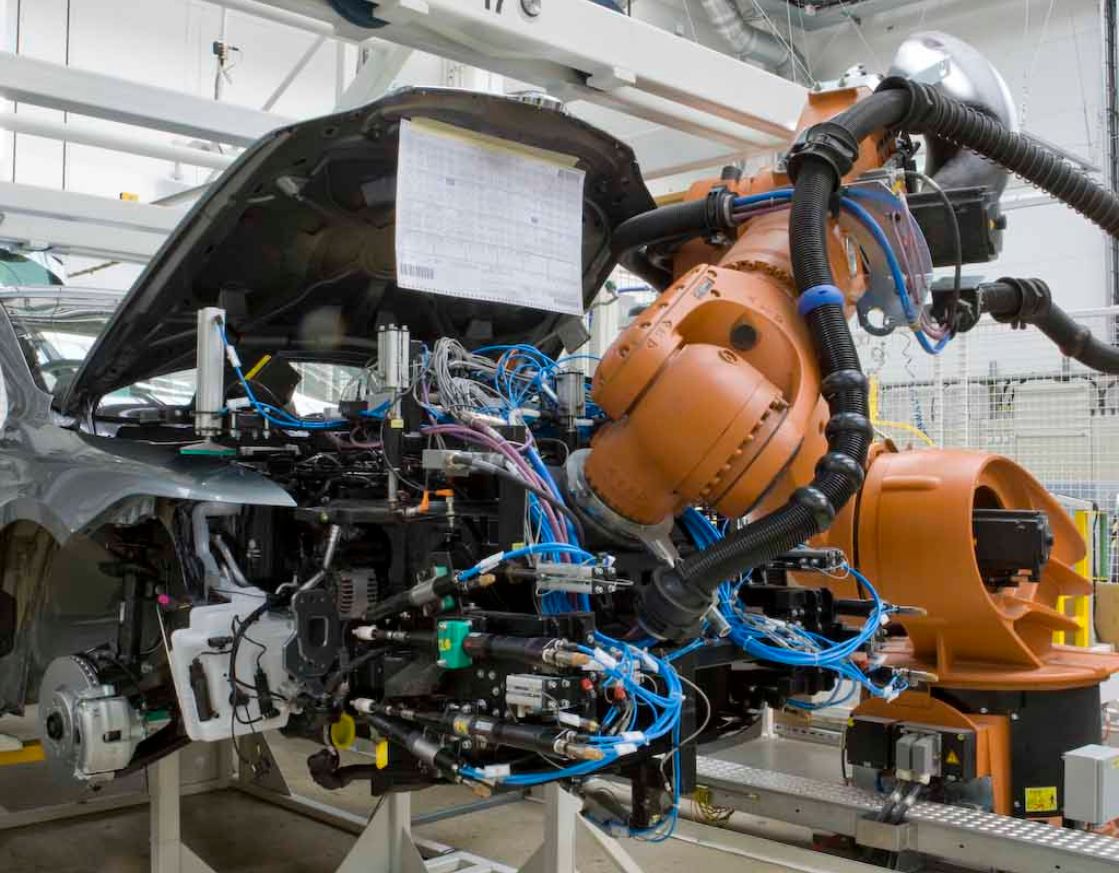
Another example of the application of camera navigation systems in robotics is the fitting of the front of the car (the so-called Frontend) on the assembly line.
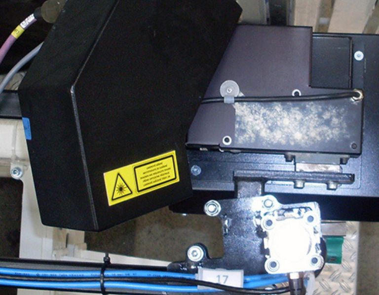
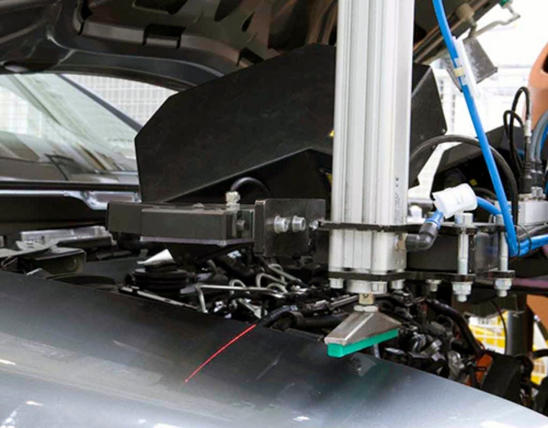
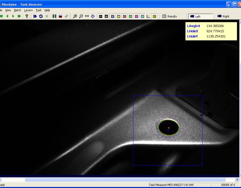
After grabbing the front, it is necessary to fit it precisely into the body to guarantee the required dimensions of the front joints of the front of the car. To achieve the right result, we use special camera modules that measure in 3D with an accuracy of 0.1mm. After measuring the body position, the robot receives the corrected body position coordinates and thus the two parts of the car are precisely saved.
The routine coordinate measurement and correction sequence typically takes less than 2 s. The scanned data is archived for the possibility of further statistical processing with the option of sending the resulting values to the superior system.
Part of the solution is unique 3D camera calibration, which runs on its own program, takes a few seconds and does not require operator intervention. This minimizes downtime of the assembly line to a minimum.
| Parameter | Value | Unit |
|---|---|---|
| Measuremet accuracy | ± 0,08 | mm |
| The smallest size of the monitored area | 10×10 | mm |
| The biggest size of the monitored area | 200×200 | mm |
| Color shades | without limits | – |
| Scanning velocity | <1 | s |
| Dimensions of the camera module (w×h×d) | 280×100×180 | mm |
| Interface between camera module and robot controller | Ethernet | – |
| Ambient temperature | 5 – 35 | °C |
| Voltage | 24 | V |


